Kev installed this full-sized tachometer on his Jackal. Note that the wiring on Stone's may differ, so take care in applying this information. If you would like to contact Kev regarding this process, e-mail me below and I can forward your request.
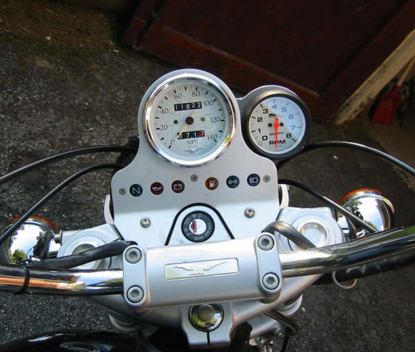
I've installed a Procycle (by Autometer) 1-2 pulse, 8000 rpm Tachometer to my 2000 Jackal. The unit is their part # 19325 and retails for about $250, though I think I paid a tiny bit less. This particular part number is a black bodied, white face, 2 5/8" unit, though they also come in chrome.
For mounting I've chosen to go with a custom billet aluminum housing sold by DBcycles (a former MG dealer who now works out of his house and on Ebay, I don't do ebay so I don't have a link for you, but here is his email addy: DBCYC@FRONTIERNET.NET ). DB stands for Dave Brown.
The bracket is basically a slightly irregular "figure 8" with a 3 5/8 in. opening that fits over the back of the stock Jackal speedometer housing and a smaller 2 5/8 in. opening for the tach. The bracket has a split machined at the middle of the figure 8 with a small allen head bolt to clamp them together. It looks good, especially how it fits the tach into the arc of the speedo-housing to the lower left or right of the speed itself.
The bracket is not perfect as the one I got doesn't quite grip the speed housing perfectly and I need to retain it with a bushing underneath and/or a clamp behind it to keep it from working loose (more on that when I'm finished in a couple of days) HOWEVER, it was only $30.
The wiring on a stock Jackal is FREAKING CAKE, as the wires are already in the instrument pod underneath the speedometer. Getting them out is another story. Email me if you need help with this task, but essentially you remove the headlight for access (I matchmarked it first to the brackets on either side to make alignment easier later), then remove the 3 machine screws which thread into the plastic of the idiot light/instrument pod housing (STUPID CHEAP DESIGN). Unfortunately this frees 3 metal bushings through which the screws were threaded to fall into the housing (during installation put the screws through the mounting holes in the dash panel and use a dab of dielectric grease to hold them on the screws, then gently align the housing with the screws and start them all before tightening).
Ok, back to disassembly, once the 3 cluster screws are out GENTLY pull the housing back for access and remove the 2 remaining screws (one on the inner end of each of the 2 idiot light clusters. Pull out the clusters and wiring and LOW AND BEHOLD, you'll find 5 wires, of which you'll only need 3 for this tachometer or others of its ilk.
Now the generic Auto Meter instructions say to wire the tacometer
Red wire to fused battery positive Black wire to ground 2 Green wires - either both to the Tach signal output from the ECM/Ignition Module OR one each to each of the negative sides of the coil primary circuits.
Referring to Carl Allison's Jackal Wiring Diagram that I downloaded a while ago... GET LINK The pre-existing wiring for a factory tach is
Tach signal - Yellow/Black wire from Terminal 3 of the ECM
Keyswitch controlled Bat + for lights/instruments – Yellow wire
Ground – 2 Black wires (no surprise, except I haven't figured out why there are two) –
And there's one additional wire, I think it was black red. Frankly, you don't need it for this style aftermarket tach.
The wires are all covered with protective rubber or plastic clips. Leave them in place on the black red wire and on the black wire with the ring terminal (unless the tach you're using would be better suited to ground with the ring terminal wire as opposed to the black wire with a spade connector).
The Yellow, Yellow/Black and one of the Black Ground wires all have female spade connectors, so I've purchased Male spade crimp connectors to attach to the Autometer leads and it is simply a plug and play installation.
RED Autometer power feed to the YELLOW Moto Guzzi harness wire power supply.
BLACK Autometer ground lead to one of the BLACK Moto Guzzi harness ground leads.
both GREEN Autometer Tach pulse input leads to the Yellow/Black Motor Guzzi harness pulse signal from the ECM.
Fired it up and works like a charm. I haven't checked it with my digital timing light yet, HOWEVER, she fired up went to 2000 rpm on full idle advance (the lever on the left grip) and dropped instantly to 1000 rpm when I took it off advance (or maybe just a tiny bit below that), so I'm almost certain she is reading correctly. I'll come back and edit this if I learn any other change was necessary.
E-mail: marina@armory.com
Copyright 2005 - Marina M. Gerson