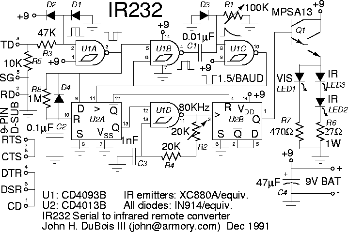
A Serial Infrared Remote Controller

|

|
I have a menu-based front end for the command line driver program described below, and use the SCO usemouse utility to let me move around the menus with a mouse. My then-housemate Ford wrote a similar front end that brings up a menu on an X display.
When I first made the remote control transmitter, the only means I had to decode my remotes (so that I could transmit their codes) was to observe the output on an oscilloscope. I would first examine the output of a phototransistor with the remote directed at it, to get the exact timing of the basic codes. Then, I connected the 'scope to the output of a Sharp 40KHz IR receiver/demodulator (the one sold by Radio Shack, labeled GP1U5(2X) or GP1U5(21X)) to record the codes. The Sharp module has turn on/turn off times that vary with received intensity, etc., but once I knew how many 40KHz cycles were in each of the possible on-times and off-times, the Sharp module was good enough to get the codes, and having the signal demodulated made it easier to read. Still, my 'scope doesn't have storage capability, so I had to keep pressing each button while transcribing its codes from the 'scope. And the basic codes are long enough that I had to set the 'scope to 10x sweep and examine the output section by section. That sufficed, just barely, to let me get the codes down, but I probably pressed every button on each of my remotes more than 100 times, and I ended up with several transcription errors which I caught when the transcribed codes didn't work.
Other ways of recording the codes are to sample the Sharp module through a PC parallel port or with a sound board. But, what I really wanted was a scheme suitable for permanent use so I could let my system keep track of remote commands sent to the equipment, so that it would always know the state of the equipment. Both the parallel port and the sound board scheme require constant polling and analysis of the line level, making them unworkable for permanent use.
I finally got around to designing an IR remote receiver that detects when a transmission is occurring and sends received data to the system through a serial port. It's a simple device consisting of registers & gates (no CPU). The receiver samples the output of the Sharp receiver/demodulator at 19.2 Ksamples/s, and sends the data to the system at 38400 Baud (to allow start and stop bits to be added). Unfortunately, I've found that the Sharp module does not work reliably with all of my remotes at reasonable range. One possibility is to get a universal handheld remote with higher power output and use it instead of the original remotes. However, I haven't yet found one I like. The other possibility is to replace the Sharp module with circuitry of my own design. Meanwhile, the device does a great job of decoding new remotes that I acquire, since when I'm analyzing them I can use them within close range of the receiver.
I wrote a program to take the serial data from the receiver and convert it to the command code that identifies the button pressed. All of my remotes encode the bits of the command number by varying either the on-time or off-time of the carrier, so I found I could recover the command number bit stream by counting the number of samples between rising or falling edges in the data stream. For example, I do:
ird -t23,35 /dev/ttyf4This tells the converter to listen on ttyf4, and convert 23-sample-long cycles to 0 and 35-sample-long cycles to 1 (the actual counts may be within a specifiable jitter range of 23 and 35). The output looks like:
<51>000000010001   11
<51>000000010001   11
<51> indicates that a 51-sample-period cycle was detected, which is outside of the two ranges it's looking for. It's actually the prefix sent before all of the commands by this remote. After that is the code, and its value in hex. The remote transmits the code twice when a button is pressed.
The next steps, most of which are in various stages of completion, are to:
Note: I do not have either kits or commercial products for sale.
Here are:
| This web page maintained by John DuBois |