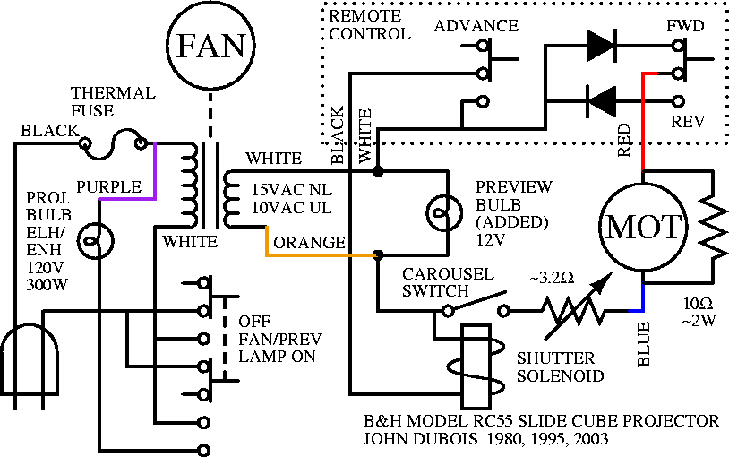
I disassembled my first slide cube projector shortly after I bought it in 1980, in order to understand it and to add a preview bulb, so that I could scan through slides without having to have the main bulb on. While I was at it I drew up a schematic of the projector for future reference. In 1995 I disassembled my projector again when the motor let out its smoke and took some other components with it, and drew another schematic because I couldn't find the old one. Later I found the old schematic filed away in the owner's manual. This is a schematic of the B&H Model RC55 drawn from both of the earlier schematics and updated, available as:

How the transformer works:
When the main switch in is the OFF position, neither contactor closes a
circuit.
When the main switch is in either the FAN/PREV or the LAMP ON
position, the upper contactor energizes the transformer, lighting the preview
bulb and enabling the carousel motor circuit.
When the transformer is energized, the fan is also on; the same windings act as
a transformer and as the windings of a synchronous motor that turns the fan.
Power is applied to the transformer through an 84°C thermal fuse (thermal
cutoff) that is seated in the transformer core, which will shut down the
projector if the transformer overheats.
When the main switch is in the LAMP ON position, the lower contactor
energizes the bulb by placing it across the primary of the transformer,
so that it receives the same 120V that the transformer does.
This is slightly different than connecting the bulb directly to the mains in
that this means that the bulb also gets its power through the thermal fuse, so
if the fuse blows, both the transformer and the bulb will be shut off.
If you have the projector open and upside down, the transformer secondary leads
and the 120V connection to the thermal fuse are on the bottom, and the primary
leads and connection to the projector bulb are on the top.
Replacement thermal fuses are available.
How the carousel circuit works:
When the ADVANCE switch is pressed, the transformer secondary is connected to the shutter solenoid, causing the solenoid armature to pull in. The armature movement does three things: it closes the projector shutter so that the movement of the slides is not seen, it closes the carousel switch, and it pulls a pin out of a detente in the carousel and so allows the carousel to rotate. The closure of the carousel switch causes current to flow through one of two diodes, depending on which position the FWD/REV switch is in. The diode allows current from only half of each AC cycle to reach the motor. The carousel motor is a permanent-magnet DC brush motor, so the direction of current through it determines the direction in which it turns. By selecting the diode, the position of the FWD/REV switch determines which half of the AC cycle flows through the motor and so determines the direction in which the motor turns.
As soon as the carousel moves slightly away from the projection position, the pin-and-detente mechanism prevents the armature from returning to its original position even when the ADVANCE switch is released. The carousel switch remains closed and continues powering the motor until the carousel advances to the next projection position. At this point, another detente passes under the pin, allowing it to return to its former position. The pin immediately mechanically stops the rotation of the carousel, and the movement of the pin into the detent causes the shutter to open and the carousel switch to open, turning off the motor.
The rheostat is used to set the motor speed (the 10Ω power resistor connected across the motor reduces the load sensitivity of the voltage reduction provided by the rheostat). If the carousel turns too fast, the pin may not have time to move into the detente as the detente passes underneath it. This can be a particular problem if the solenoid spring is old and not exerting enough force, or if any part of the mechanism attached to the solenoid armature (particularly the shutter blades) has gotten gummed up. The solution to this is to do one or more of the following:
| This web page maintained by John DuBois |