The EPROM programmer presented here is capable of programming all 2764, 27128, 27256 and 27512 EPROM's that have 12.5 volts VPP. This will cover almost all 28 pin NMOS and CMOS EPROM devices. Also in the future an upgrade to the software should allow it to program EEPROM's.
The unit runs from a parallel printer port on any IBM PC or clone machine under DOS. The software will run under Win95 in a DOS window but the timing of the writes will be incorrect and therefore it is not recommended. The software has not been tested on any machine slower than a 386/16.
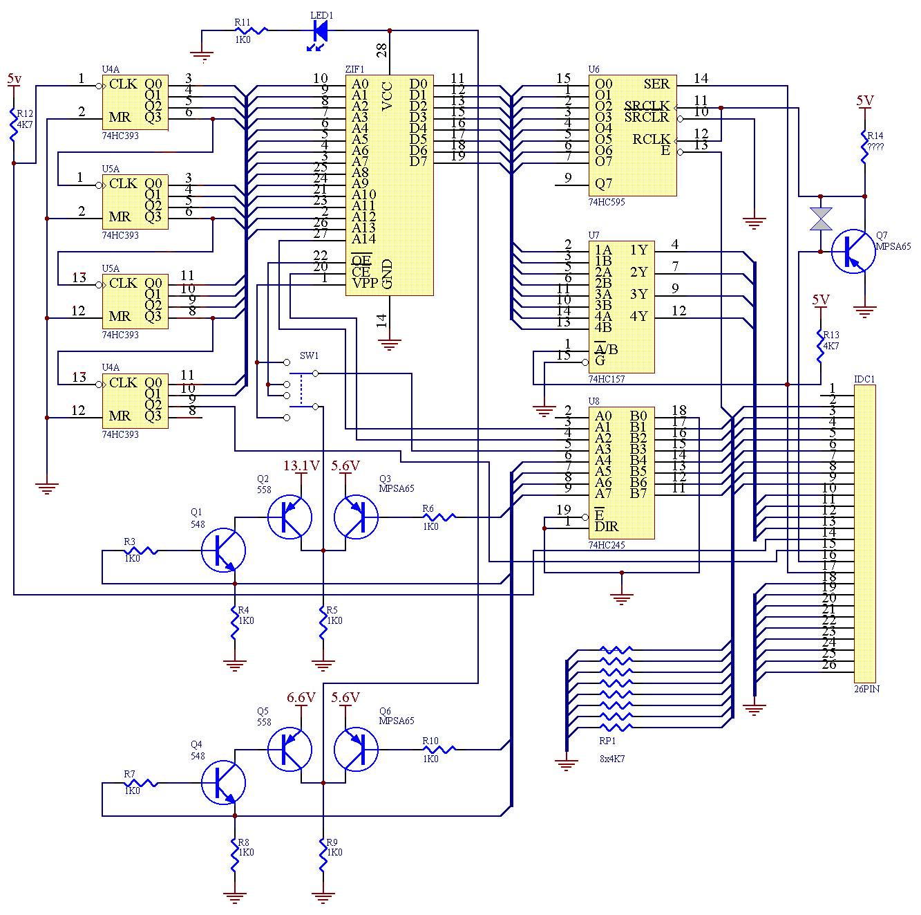
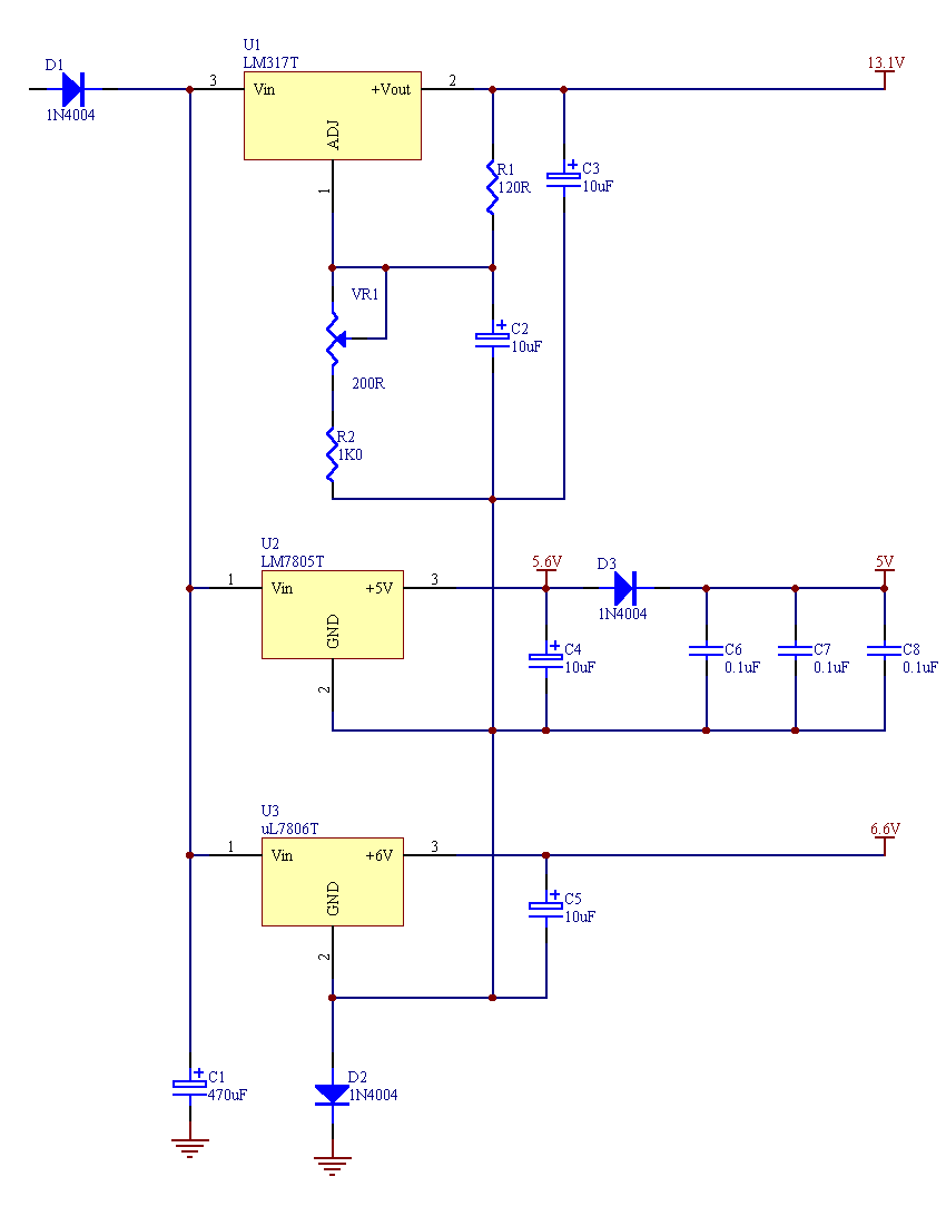
Shown in the two pictures above are the schematic for the EPROM programmer and it's on board power supply. There is nothing to out of the ordinary that should need explaining in the circuit.
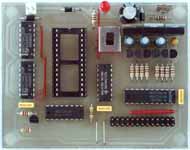
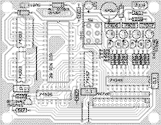
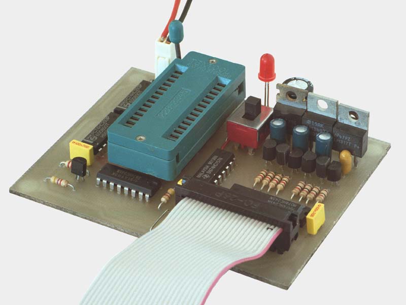
Above is shown a picture of the board viewed from above and an overlay diagram. Clicking on either picture will show the same picture expanded. Any component on these expanded pictures can be clicked upon to shown its detail in the parts list. Use these as a guide to installing all of the components in the PCB.
A few points to aid in construction are
One more very important thing. The metal tabs on the back of the TO-220 packages (the 3 vregs in the top right) are connected to pin 2. This means that the one on the far right is at a different voltage to the other two. After installing them if there is any chance that they will touch wrap the metal tab in sticky tape to insulate them. If they touch you will blow something up.
Finally you have to decide if you need to install Q7 and pick a value for R14. This is dependent on the type of 74595 you have installed. The table below will tell you what you should use.
| Chip Type | R14 | Q7 |
| Any LS | 4K7 | NO |
| Texas HC | 560R | NO |
| Motorola or other HC | 220R | YES |
|
If Q7 is installed then the track on the PCB between the X needs to be cut. |
||
Q7 is used to sharpen the rising edge of the clock signal and will not harm the Texas HC or the LS chips so to be safe you can always install Q7 and use a 220R resistor. Everything will still work and omitting Q7 only saves 40 cents.
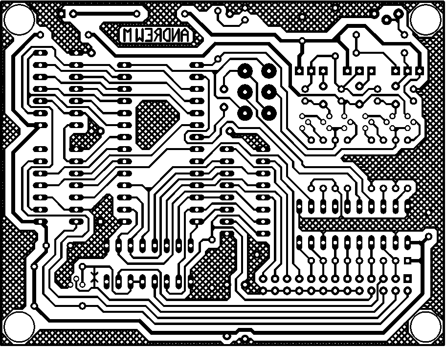
Below is picture of the PCB (again click to enlarge). The size of the PCB was kept small enough to fit onto one of the standard 150 x 74mm boards that are available throughout Australia. The protel easytrax file EPROM132.PCB can be downloaded here.
After you have finished constructing the programmer plug it into an AC plug pack (12VAC is specified but a 9VAC unit will work and the heat sinks will run cooler). With the unit powered up make sure that there is about 5 volts at all of the IC's (between the last pin and the diagonally opposite corner). Also check that there is no more than about 5 volts on any of the pins on the 26 way header.
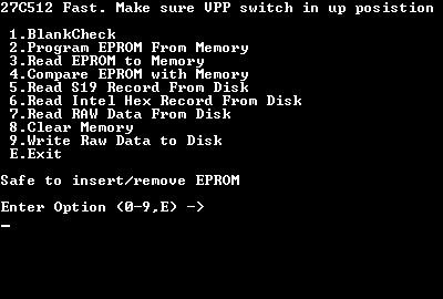
If both of the above tests check out plug the unit into the PC and run the program TESTHW.EXE. You will be shown a screen that looks like this (though not all the lines will be there yet).
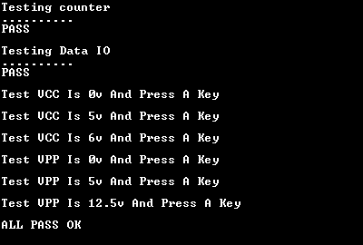
When the software is first run it will test the counter and the data lines. After these check out OK it will ask you to test the voltage on the VCC pin. VCC is the pin in the top right hand corner of the 28 pin socket. After this VPP needs to be checked. Put the switch in the UP position and VPP will be the pin in the top left hand corner of the 28 pin socket. When VPP=12.5volts is being checked the trimpot in the top right hand corner of the PCB can be used to adjust it.
If all seems OK run-test the unit by programming and verifying and EPROM.
The software is totally free and can be downloaded from the URL's below. However it is not Freeware. It is a slightly different concept called Great-Guy-Ware. All you have to do if you wish to use the software is send me an E-mail telling me I am a great guy. This serves two main purposes. One is to make me feel good and secondly it encourages me to finish some of the other articles I may have started in the last ten years.
The software is contained in the main zip file
eprom.zip here (598K).
Its is also available by itself
software.zip here (180K).
The programmer uses different executables for different EPROMS as outlined below.
| EPROM Type | Fast Program | Slow Program |
| 27X64 | F64.EXE* | S64.EXE* |
| 27X128 | F128.EXE* | S128.EXE* |
| 27X256 | F256.EXE | S256.EXE |
| 27X512 | F512.EXE* | S512.EXE* |
| * Indicates beta version not tested extensively | ||