Negative Voltage Generator
Discrete Version

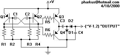
This small image does not include part values. If you intend to redistribute this circuit elsewhere, it is imperative that you distribute the larger version, complete with parts list and text writeup. You can get the large version by clicking on the small version.
Click here to see photos of this circuit in operation
Why do we need this?
Most operational amplifier circuits require a dual-polarity power supply - one having +V and -V. However, there are times when a DP supply simply isn't conveniently available. Single-polarity modifications to DP designs often acheive their effect by referencing the input to a "synthetic ground", derived using a resistive voltage divider. This renders the resulting circuit highly sensitive to power supply noise, since any variation in the power supply will be divided by the divider, then used as an input reference, and amplified by the circuit in question. While this is of little concern with battery sources, AC "wall-warts" and many DIY power supplies are chock full of horrendous 60Hz buzz that is sure to get into the circuit.
By powering an op amp with a dual-polarity supply, we are able to reference all signals to a definite solid 0V ground.
This circuit starts with a single-polarity (GND and +V) input and produces an approximate opposite voltage (-V), enabling dual-polarity op amp circuits to be used with single-polarity supplies.
Theory of Operation
Q1, Q2, C1, C2, R1, R2, R3, and R4 form a multivibrator -- an oscillator. We are using both of its outputs which are opposites of one another: when one is on, the other is off. These outputs go through R5 and R6 to turn on Q3 and Q4 - one at a time, of course. This applies a wave oscillating from +V to GND to C3. This is where things get interesting.
Q3 and Q4 form a current amplifier. When Q3 is turned on, +V is applied to C3. We can envision the current going through C3 and D1 to ground. This charges C3. Next, Q3 turns off and Q4 turns on, applying GND to C3. C3's + terminal is now at GND. Since C3 is charged to nV, its - terminal has to be n volts below its + terminal, meaning that its - terminal is n volts below GND. This goes through D2 and is our output. C4 is a filter capacitor for -V, and serves up the current filling in the gaps when C3 is charging.
Parts list - No part values are highly critical.
| Resistors | A word on capacitors: Somewhere along the line, I learned that the symbol for a non-polarized capacitor is two straight lines, and a polarized electrolytic gets a straight one and a rounded one, the straight one being +. I adhere to this, although most people don't. I also don't mark + or - next to them. In the schematic above, the flat sides of C3 and C4 are the + sides. | |
| R1 | 1K | |
| R2 | 10K | |
| R3 | 10K | |
| R4 | 1K | |
| R5 | 1K | |
| R6 | 1K | |
| Capacitors | ||
| C1 | .1uF | |
| C2 | .1uF | |
| C3 | 1,000uF | |
| C4 | 1,000uF | |
| All transistors: | 2N3906 General Purpose PNP | |
| All diodes: | Generic silicon rectifiers | |
Notes
Output is not exactly -V. Due to the drop of the transistors and diodes, the magnitude is theoretically reduced by 1.2V. In practice, it varies a bit. This is suitable for powering op amp audio circuits using negative feedback. See usage suggestions for more information.
Usage Suggestions
Due to voltage drop, it may be desirable to power this circuit from a source of at least 5V above the desired magnitude and use voltage regulators on both rails to derive the intended voltages.
Improvement Suggestions
Current capacity may be increased by using a couple of comparators (or a 1458) to ensure that the current amplifier transistors remain in switch mode, as well as by using complementary (NPN and PNP) power transistors in their places.
I have made these modifications on paper, but have yet to try them. I will post the modified circuit here if it works.
Additional
This circuit was built in a pinch because I needed to power a microphone preamp from an unregulated, noisy, single-polarity 12V supply that also powers a couple of power-hungry sirens and a video camera. While said preamp is now working relatively successfully, this circuit is a quick design that has not been put through extensive testing. I do not know its current limitations. Some components on the board can be heard to be "whining", much like a switchmode power supply. This does not indicate a problem, as none of the components run particularly hot. Also like a SMPS, this noise is slightly detectable on the output. A linear voltage regulator should cure this, although it is not a particular problem in the circuit's intended operation (op amp audio circuits using negative feedback)