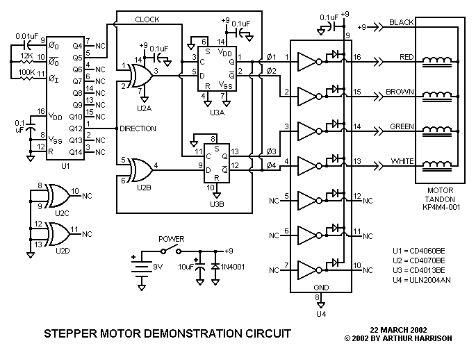
This circuit controls a small, four-phase, unipolar stepper motor. This type of motor was used in 5 1/4" floppy disk drives in older computers. Now obsolete, many such disk drives are available on the surplus market for little or no cost. The stepper motors are easy to extract from the drives, and are ideal for many applications. This arrangement was used in the scale model of a RADAR set to control the position of a miniature parabolic antenna.
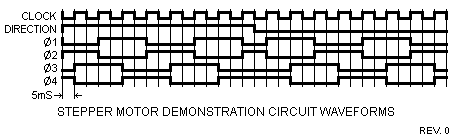
Referring to the schematic, U1 contains a relaxation oscillator and a binary ripple counter. U1's Q5 output provides a 100 Hertz square wave for the clock inputs of "D" flip-flops U3A and U3B. U1's Q12 output provides a level that alternates between "low" and "high" logic levels every 64 cycles of Q5. This signal is applied to the inputs of exclusive-or gates U2A and U2B. The flip-flops and gates form a quadrature waveform generator with complimentary outputs. These waveforms are applied to U4, a set of Darlington drivers capable of providing the required sink current for the motor. The waveforms and their relationships are illustrated in the following figure.
The motor rotates one step, or 3.6 degrees, for each positive clock transition. Rotation occurs in one direction for 230.4 degrees (64 clock cycles x 3.6 degrees), and then reverses. Clockwise rotation occurs when U1's Q12 output is a logic "high" level, and counterclockwise rotation occurs when it is "low."
If desired, pins 2 and 5 of gates U2A and U2B may be disconnected from the counter, and alternatively provided with an external direction control signal. The 12K timing resistor may be substituted with other values, with greater resistance decreasing the motor's speed. The maximum speed is determined by the motor's mechanical characteristics and load torque. For the prototype, operating at 9 volts, the clock frequency could be increased to 250 Hertz, while still providing smooth operation.
The circuit uses about 160 milliamperes at 9 volts, with a majority of the
current consumed by the motor. Therefore, a power supply is recommended in
lieu of a battery if continuous operation is desired. The circuit will operate
from 6 to 12 volts, depending on load torque and speed.
March 22, 2002
Text and images ©2002 by Arthur Harrison
Back to the Circuit Library Index
Back to the Opening Page of Art's Theremin Page