
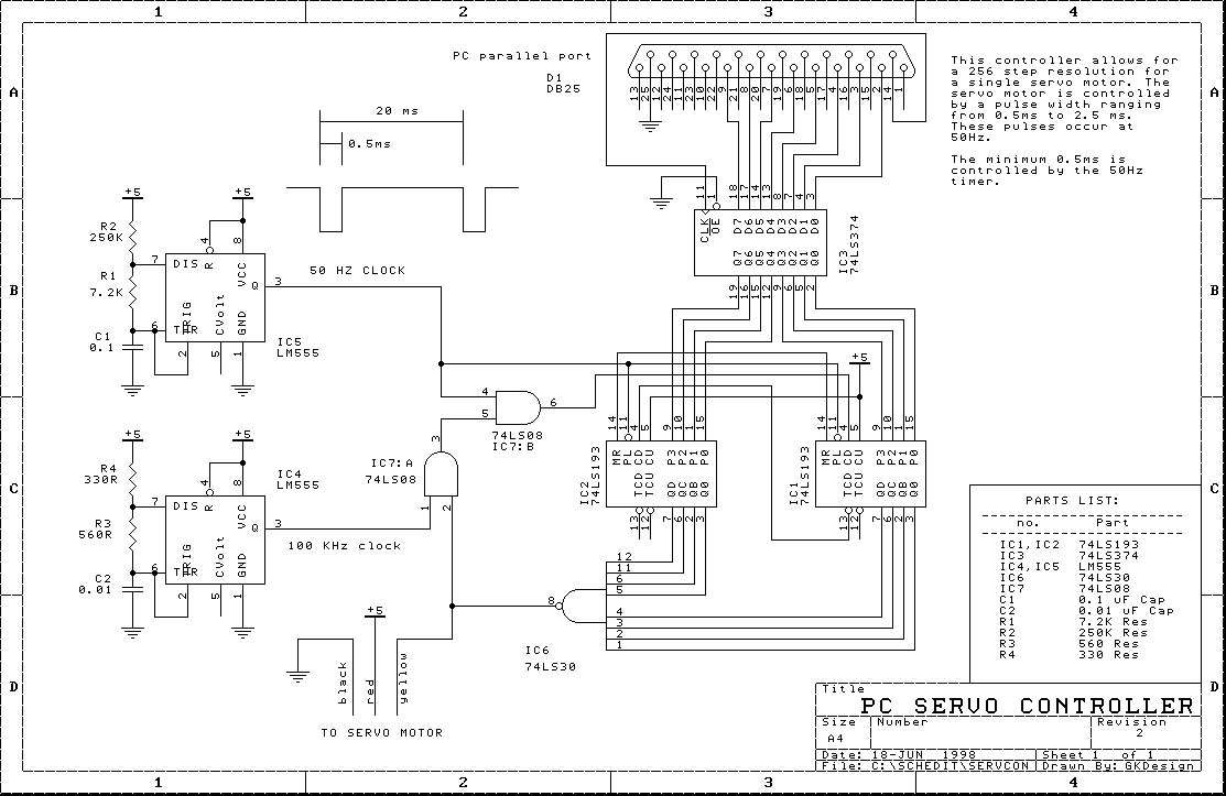
This circuit was designed for controlling a servo using the PC's parallel port, and I have found it useful for doing robotics experiments at home. The servo is the standard three-wire type used in model planes and cars, where the servo control is achieved via pulse width modulation (PWM).
Most of these types of servos require a 50Hz clock, whose pulse width varies from about 0.5ms to 2.5ms. This range of values usually gives control over the servo's limits. This circuit gives you 256 different positions over the full range of the servo, which should be more than enough for most applications.
The circuit is based on 2 clock sources and a countdown timer. The first clock is based on a 555 timer and providws the 50Hz signal. The pulse width of this signal is the minimum pulse width (0.5ms) needed by the servo. This value may be increased or decreased depending on the particular servo used, and this can be achieved by varying the value of R1.
This signal is then used as a gate control for the 100Khz clock signal produced by the second 555. This gated signal is used to supply a clock to the countdown timer consisting of the cascaded 74LS193's. A 100Khz signal is needed to provide the resolution of 256 steps in 2ms.
To set the position of the servo, a value ranging from 0 to 255 is written into the octal latch (74LS374), and this value is then loaded into the countdown timer on the next 50Hz cycle. The timer then begins to count down from the set value until -1 (11111111b) is reached. This causes the 100Khz signal to be disabled and no further counting takes place until the next 50Hz cycle re-loads the value from the octal latch, and the counting resumes again.
The 74LS30 eight-input NAND gate connected to all the outputs of the counter serves as an OR gate here, which outputs a high while the counter is counting. The output of this gate is the drive signal sent directly to the servo motor. I haven't found it necessary to buffer the signal to the servo, but a buffer stage can be added.
One important aspect of the design is that the position value can be written to the controller any time, and the computer can communicate asynchronously with the circuit. This allows the computer to do other tasks while the controller handles all of the timing necessary for the servo.
A simple control program (written in Borland 3.1 C) is:
#include <dos.h>

#define DATA 0x378
#define CONTROL 0x37A

void servo_position(unsigned char value)
{
	outportb(DATA,value); // write data out to the parallel port data bus.
	outportb(CONTROL,0x00); // This has the effect of producing a pulse
	outportb(CONTROL,0x02); // on the linefeed control line of the parallel port.
	outportb(CONTROL,0x00); // This is used to store the data in the octal latch.
}
[Home] | [Publications] | [Past Projects] | [New Projects] |