Interfacing Sony control stick to Empeg


Sept. 4, 2000

After discovering that others had interfaced wired remote controls to their Empegs (including Sony control sticks) I decided to try to do it with the fewest components possible.

You may find that there are too few, if your power is very noisy (as can happen in a car environment) it may help to place a 0.1uF and/or 10uF capacitor before and/or after the voltage regulator. At the moment I'm not using these but at this point I've only tested it on the bench, not in the car. I'll update this web page after it's all installed.


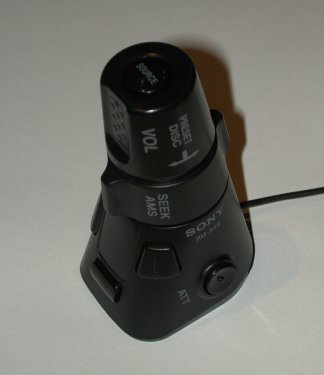
I used a Sony RM-X4S rotary commander, but I believe the RM-X2S is compatible. I picked mine up at a local car audio installer, they had it in stock and I hear they're quite commonly available.


This design is meant to be as simple as possible that means there is no extra protection. If you connect pins of the serial port wrong (including reversing transmit and receive) you will destroy the PIC. The 0.1uF capacitor on pin 3 is a critical component, get the most accurate you can, don't just pick up a 20% ceramic disc from Radio Shack!

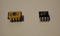
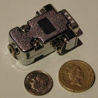
Be aware that the 78L05 in a TO-92 package (chosen because it's phyically smaller) has a pinout that is backward compared to the 7805 in a TO-220 package and compared to the schematic. The drawing to the left shows the correct pinout.


The following table shows the function of each control under three source modes.
(directions assume stick is mounted pointing to the right)

 EmpegRadioAux
ATTPlay/PauseMuteMute
OffOn/OffOn/OffOn/Off
SourceRadioAuxEmpeg
Vol knobVol Up/DownVol Up/DownVol Up/Down
Seek ringTrack Next/PreviousPreset Next/Previous-
Push+twist vol knobFast forward/RewindTune Up/Down-
Front buttonVisual selectVisual selectVisual select
Rear buttonScreen mode selectScreen mode selectScreen mode select
Bottom buttonShuffle On/Off--

Commands are sent to the Empeg at 4800 baud, so you'll need to have the latest image loaded onto your empeg and have it installed into the docking sled for it to work. (Empeg's baud rate defaults to a higher speed if not docked, or when using older versions of the code.)


PIC code for stick mounted pointing right or up:

Source code in Parallax assembly Sony4.src (for the curious only)
Pre-compiled object code for the PIC12C508 SONY4-508.OBJ
Pre-compiled object code for the PIC12C509 SONY4-509.OBJ

PIC code for stick mounted pointing left: (up/down controls reversed)

Source code in Parallax assembly Sony4b.src (for the curious only)
Pre-compiled object code for the PIC12C508 SONY4b-508.OBJ
Pre-compiled object code for the PIC12C509 SONY4b-509.OBJ


You may use either the PIC12C508 or PIC12C509 depending on which you have laying around. Be warned that they come from the factory with a calibration value loaded into the highest address (01FF for a '508 or 03FF for a '509). This value must not be erased or overwritten!


If you are using a windowed package (shown on left) you must read this value and write it down before you erase the chip. When you re-program the chip later, be sure to re-program this value. If you are using a black plastic chip (shown on right), either set your programmer not to program the "calibration value" (there may be a checkbox) or read the chip first, write down the value in the upper address on a piece of paper, load the object file and manually type the value you wrote down back into the hex view before programming. If you don't do this right and the calibration value is changed, the program will not work.


This project is so small, you can fit the whole thing into the DB-9 shroud!


Back to my home page