A 16x16 LED Matrix
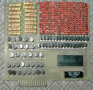
I prototyped the design by building a single row from it on a solderless breadboard. The row worked properly - I could scan through my single-LED “columns” - so I set about designing & laying out a printed circuit board with the same column scanning circuitry but 16 of the rows. It was incredibly tedious because there were no CAD tools available to me. Most printed circuit board work was still done with vellum & acetate at the time, so that's the method we were taught in the electronics program (and in any case, back then I'd never laid hands on a computer more capable than a Commodore 64). So, I sat down with my trusty 2X printed circuit board drawing template and drew 512 pads for the LEDs and another 246 for the other components - 64 transistors (I used 2N3906s and 2N2222s because pairs of them were cheaper than Darlingtons), 16 resistors, etc. Then I connected them together according to my schematic.
Next came the really laborious part - laying all those pads and traces down on acetate using dry transfers! This was a little unusual in that I had packed the LEDs so tightly that there wasn't room for both pads on each side. Instead I put the column pads only on the component side; I used DIP pads for them, and they were close enough that the pads merged together. On the trace side I put only the row pads, using circular pads connected by a trace - the LED leads were arranged horizontally, so I couldn't just merge the pads together. The connections were of course made with black tape.
Finally it was finished. By this time I had completed the electronics program, and so didn't have automatic use of the lithographic equipment. I probably could have begged the use, but since I planned on doing many circuit boards in the future, instead I made my own lithographic camera using particle board and a photocopier lens from ETCO (or maybe it was Herbach & Rademan - it was a long time ago!) The camera worked perfectly; I was able to reduce my 2X acetate designs (trace side traces/pads, component side traces/pads, and common pads) to two 1X masks (trace and component side).
I'd been using photo-etch equipment at home for a while, so making the PC board was easy enough. I had a little battery-powered PC board drill made by OK, complete with a minimalist sort of drill press for it - the drill could be attached to a spring mount that let it be pressed down to drill a hole. It worked, but made me wish for the real presses the electronics lab had.
Soldering the components on was a challenge due to the LEDs. The column leads obviously had to be soldered on the component side, and the LEDs were tightly enough packed that I had to carefully solder in columns of LEDs from left to right; there was no way to access the solder joint once another column blocked it. Also, I had arranged the holes such that the leads needed to be bent in toward each other so that the pads were evenly spaced, which worked fine, but at the top the leads pressed against each other (the LEDs had axial leads, which I bent at a 90 degree angle). I put pieces of cellophane tape between them to insulate them.
When it was all done, I connected it to a circuit that scanned through the columns, and turned on all the rows. A couple of LEDs didn't light. Replacing them was difficult due to the component-side column pads, but I eventually managed to do it. It was completely functional!
I worked up some circuits for solid-state oscilloscopes and such. But I never built them. After all that work, as was my wont, I got sidetracked on other projects, and so the LED array gathered dust for four years, never having done anything but light up. In 1986 I transferred to UCSC, majoring in computer science, and most of my attention was diverted to computers and software.
But, in 1987 I took a class in computer interfacing. For my final project, I decided to drive the LED array from a PC. The obvious means of doing this was through the parallel port. For simplicity, I would have the PC do all the matrix-scanning work. I had just gotten my first PC, an 8 MHz 8088, earlier that year. I was just familiar enough with them to understand the Centronics printer protocol, but did not know how to drive the parallel port directly myself. So, I would go through the DOS parallel port driver (lpt1), and make the hardware emulate a printer to the extent of responding to a /STROBE with an /ACK.
Because I went about it in this way, I had only the eight data pins to play with - those that I could control by writing data to the parallel port driver. I designed a circuit that would use four of the pins for data, three for an address, and one as an output latch signal. Of the eight possible addresses, four went to the latches that would hold the data for the 16 rows, one went to the column-select latch, and the others were unused. I used the parallel port's /STROBE signal for first-stage latching. Displaying a column required this sequence of five bytes to be written to the parallel port driver:
As it turned out, even with the PC doing nothing but running this trivial application, it was barely able to scan the display. Getting the 80 bytes that were required for a full display refresh through Turbo C's printer writing routines and in turn through the PC's parallel port driver involved enough overhead that an 8 MHz machine could barely avoid having the display flicker. But it did work - at last I had done something with the LED matrix!
Since then it has, you guessed it, gathered dust. I put so much work into it that I do still plan to do something further with it some day, certainly involving leaving the scanning up to a microcontroller. I might put a fast lens in front of the LEDs and use it to project a clock onto the ceiling or something.
Meanwhile, I get periodic mail about the LED matrix, mainly as a result of a Usenet News article that I posted in 1991. I've had requests for contruction information for the project. At present, I have the following:
What I don't have:
| This web page maintained by John DuBois |